An introductory guide to operating DC motor using Arduino, perfect for beginners.

A direct current motor (DC motor) is a very basic type of motor. DC motor has amazing features like higher starting torque, variable speeds based on provided input voltage, rapid starting and stopping, and cheaper controlling than AC motors.
The speed of the DC motor can be changed by varying the applied input voltage. If the applied voltage is high then the motor rotates at a higher speed similarly if the applied voltage is low that means the motor will rotate at a lower speed.
I have used a 5 5-volt DC motor, for which applying a 5-volt input voltage to the DC motor will provide a higher speed while applying the lower voltage will provide a lower speed.DC motor normally has two leads one is positive and the other one is negative. If these two leads are directly connected to the battery, the motor will rotate in a particular direction. If we exchange the leads, the motor will rotate in the opposite direction.
In this article, you will learn how a DC motor can be operated using Arduino Uno. DC motor should not be operated directly by the Arduino Uno pins. It will damage the board, to avoid this situation I will use the transistor as a switch to operate the motor using Arduino. I am providing a very basic circuit connection example that will help you to understand how a DC motor can be turned on and off with the help of a transistor.
Required components
- Arduino Uno board: BUY ON AMAZON
- 1 x 2N2222 transistor: BUY ON AMAZON
- 1 x 1N4007 diode: BUY ON AMAZON
- 5-volt DC motor: BUY ON AMAZON
- 1 x 220-ohm resistor: BUY ON AMAZON
- few jumper wires(male to male): BUY ON AMAZON
- Breadboard: BUY ON AMAZON
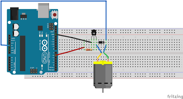
Connection diagram

Circuit description
The transistor has three terminals with two side structures (flat and round). The flat side’s first terminal should be connected with the positive terminal of the diode (as shown in the connection diagram).
The middle terminal is connected to the 220-ohm resistor and the third terminal is connected to the ground. The 220-ohm resistor’s other terminal is connected with PWM pin 6 of the Arduino board.
The motor is connected across the diode. The negative terminal of the diode is connected to the 5-volt power supply pin of the Arduino board. The transistor and diode should be connected correctly otherwise you will not get the exact output.
Code: DC motor using Arduino Uno
/*
*How to operate DC motor using Arduino uno
*
*This is a very basic example which will help you to understand how a DC motor can be turn on and off using Arduino Uno.
*
*for more detail about this project please visit:https://arduinounomagic.com/2019/03/how-to-operate-dc-motor-using-arduino.html#more
*
*Copyright (C) 2007 Free Software Foundation, Inc. <[email protected]>
*
*for more projects based on Arduino uno please visit: https://arduinounomagic.com/
*/
const int motor=6;

void setup()
{
  pinMode(motor, OUTPUT);
  }

void loop()
{
  digitalWrite(motor, HIGH);
 delay(1000);
  digitalWrite(motor, LOW);
  delay(1000);
}
Output
The motor will turn on and rotate for a specified millisecond time after that turn-off and this loop runs over and over again. You can understand the workings of the code with the help of the video provided below.
Some other important points to keep in mind
- The speed of the motor can be changed according to the need. analogWrite(pin, value) function is preferred in the code to generate PWM wave on PWM digital pins of Arduino Uno board (PWM pins are: 3, 5, 6, 9, 10, and 11). We can provide any value between 0 to 255 in the analogWrite function. The DC motor will rotate at different speeds according to the specified value (0 to 255) in the function.
- The DC motor can rotate in a clockwise and anti-clockwise direction. If the motor is rotating in a clockwise direction and we need to change the direction of motor rotation into an anticlockwise direction then the leads should be interchanged. The H-bridge is an electronic circuit that is used to drive the DC motor in both directions according to the requirement without changing the leads.
Application
How it will look like:

Making instruction
DC motor is most commonly used in multiple applications such as in toys, drones, home appliances, and so on. I have used 5 5-volt DC motor to develop a mini water pump using the above-provided code which can be used for home-based automation systems (like indoor plant watering systems and automated fish tank water pumps).
For the outer structure, I used a small plastic box with a cap. I made a hole in the center of the box’s cap to attach the DC motor and two other holes in the box to attach the water pipes (one in the center and the other one in the verticle edge of the box).
After that, I took a round shape plastic plate attached five small plastic plates to it vertically, and fixed it with the motor rotator inside the box using the glue gun. In the end, I glued small water pipes in both the holes of the box and fixed all the stuff with the help of hot glue.
(Note: I used the soldering iron to make a hole in the plastic box) After that, I attached the DC motor with the Arduino board as shown in the circuit diagram and uploaded the code and my water pump is ready to use.


Note:
Sometimes when you upload the code and try to run the DC motor while connected through the Laptop using a USB cable, at that time you may face the problem that the DC motor is not rotating due to an insufficient power supply issue. In that case, you should use an external 5-volt DC charger (your smartphone charger) to provide a power supply using the Arduino-compatible USB cable.
Hope you enjoyed the article.
If you like the article, let me know in the comments.
If you have any queries, let me know in the comments, and I will try to solve your problem as soon as possible.


 as a switch using Arduino 27")


